This series follows my attempt to develop a product that I dream of getting into the elite levels of hockey. Previously on the Quest: Part 1, 2, 3, 4, 5, 6, 7, 8, 9, 10, 11, 12, 13, 14, 15, 16, 17, 18, 19, 20, 21, Concept Launch, 22, 23, 24, 25, 26, 27, 28, 29, 30, 31, 32, 33, 34
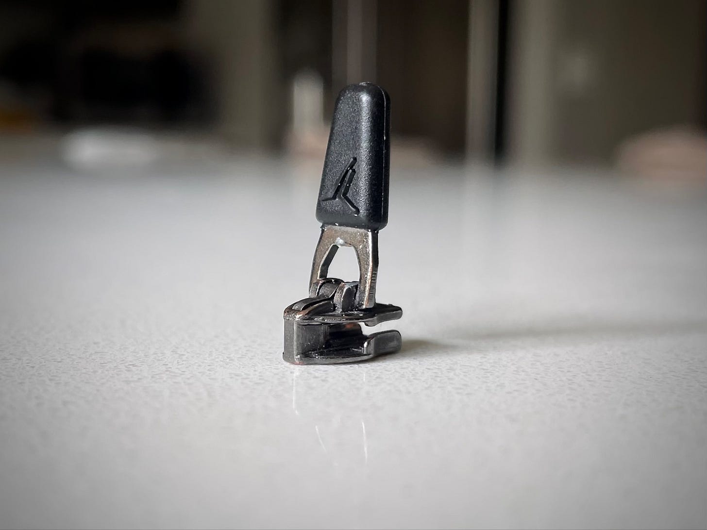
The other day, the slider from a zipper fell off of my $10 sweatpants. I went to throw it out, but something about it called to me, and I stopped to take a closer look.
On top of an incredibly intricate shape sat a hinge, which somehow managed to “lock” the pull in three distinct positions. The pull itself featured an embossed logo within a rubberized coating. A common object – and, at the same time, a testament to the powers of modern manufacturing. Just think of the decades of expertise and specialized machinery that went into its creation and imagine how difficult it would be to recreate that in your garage. Truly remarkable. So anyways, I threw it out.
Through its sacrifice, the zipper helped me contextualize the challenges I’ve been facing while building this latest version of the Uncage. There was nothing new about the steel frame I’d designed; it would be made the same way as every mass-manufactured cage out there today – rods bent and spot welded together. But newness isn’t everything. The objects we take for granted every day have so much hidden complexity. And here I was, attempting to replicate industrial processes without the expertise or the equipment.
(Quick aside: of course, I did try to get this frame made by companies who specialize in cages but it’s not really possible until I’m past the prototyping phase.)
I felt confident about the bending part at least, because I’d done it before. This time, my process was even better. It was pretty satisfying to make complex 3D bends with just a manual tube bender and a digital angle finder, so indulge me as I go into a bit of detail on how I did it.
The first step was to make a drawing from my CAD model. There were four pieces of information I included: the angle of each bend, the angle between each bend (angle of the bend plane), the length of each bend, and the length between each bend.
Next, I printed out the drawing in 1:1 scale and, using the sheet that laid out the length and position of each bend, transferred the starting point of each to my material
One end of the rod then went into my bending setup: a Ridgid tube bender clamped in a bench vice by its handle (to give me space to bend). The other end of the rod rested on a scrap piece of wood to support the magnetic digital angle finder, from which I could read the angle of the bend plane (ie, how much to twist the rod).
With the setup complete, I lined up the markings, checked the angle of the bend plane, locked the rod in place, moved the angle finder to the handle of my tube bender, and made the bend. Rinse and repeat for each of the seventeen bends
I repeated that entire process one more time for the second long bar, before turning to the U-shaped anchors that joined the two bars together (and would eventually anchor the Dyneema net). The anchors ended up being a huge pain in the ass, mostly because of the out-of-plane bends, like the one highlighted below, which helped the anchors follow the contour of the mask.
The bends were too close and too tight for my bender, so I recreated a three-point bender with three scrap tubes, a bench vice, and my face (to keep the whole shaky contraption together while I tightened the vice).
Individual components in hand, it was time to join them all together with spot welding, a process that I’d used successfully before in this project, just on a much smaller scale. No real reason to believe I couldn’t do it, but no real reason to believe I could either - considering my lack of welding experience.
Lately, I’ve been wondering if it’s naive of me to believe, after months of failures, that everything will work out. It probably is. At the same time, as someone whose internal monologue has been stuck on self-doubt for a little while, it’s nice to recognize that there’s a well of optimism in me.
I did my best with the spot welding. As you can see above, for the first attempt at the new design, I used hollow tube. I was trying to keep the weight down to match existing cages, but the thin walls presented a challenge while spot welding. The weld duration had to be relatively short otherwise I’d melt straight through the tube.
Still, everything stuck together. What more do you need from a weld? I even gave it a coat of paint to keep it from rusting.
And then, after all that care and attention, the frame exploded on the first shot.
I only hit the frame, missing the Dyneema ropes entirely, and it still exploded. Obviously, the spot welds were awful; duct tape probably would’ve been stronger.
I had planned to write an update after building and testing the first version of this new cage, but I just couldn’t. As open as I try to be about my failings, I do, unfortunately, still care what you think of me. I hoped that if I kept marching on, I’d get to a point where it looked like I knew what I was doing.
I made a handful of changes to the design before my second attempt: simplifying the anchors and tweaking the outer profile for easier bending.
But the biggest change was in the material. I chose 17-4PH stainless steel rod for its high yield strength, stainlessness, supposed weldability, and lack of thin walls (weight be damned for now).
When the material arrived, I did some spot welding tests (in other words, I whacked the welds with a hammer) and came away unimpressed. I even came up with a cheap way to precisely adjust the weld time with a programmable outlet timer. No matter what duration I tried, though, the welds remained weak. I knew I needed help.
Before I got that help, I went through the entire bending process once again. (Feel free to scroll up and read again from the beginning if you’d like to put yourself more firmly in my shoes.) And again, I spot welded every joint, but this time, the welds were just to tack the fifteen separate pieces together until they were TIG welded by someone who actually knew what they were doing.
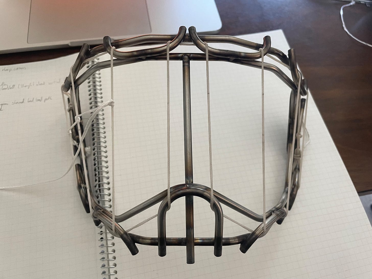
When I finally picked up the cage from his shop and felt its solidity, I was feeling optimistic. A few hours of stringing later and it was looking like the most convincing cage I’d ever built.
But it was Bob – my test dummy – who really needed to be convinced. He donned the mask and took thirty 65 mph shots like a champ. A few of the welds between the anchors and the inner of the two frame bars cracked, but the welder had told me that my well-intentioned spot welds might have contaminated his welds, so I assumed it was maybe a bit of that and a bit of flexing in the frame.
The slo-mo video revealed it was more than a bit of flexing.
We’ve seen this collapsing / clamshelling problem before and I’ve fixed it before. I thought I’d solved it before with a stiffer frame, so I made sure to match that stiffness in this new version of the cage. That, apparently, was only part of solution, but not all of it. There was also a bit back in Part 29 about angling the ropes so that the tension would partially be aligned parallel to the frame. (Boy, is that post painful to read knowing what I’m about to do.)
That’s not going to happen this time. I’m running out of time and I can’t keep choosing the wilder and more interesting ideas when there are simpler solutions right in front of me. In this case, that simpler solution is adding a vertical bar.
It’s a bit of a bummer, but also not as big of a deal as I’d been making it out to be in my head. My one objective measure for visibility is the surface area of material covering the face hole. An Uncage with a vertical bar would still have ~50% less stuff in front of a goalie’s face than a cat eye, while having the stick penetrating protection of a certified cage.
On a personal level, however, it’s a bitter pill to swallow. The critical part of me looks at the design as essentially returning all the way back to the seed of an idea that got this whole thing started a year or two ago now. Once again, those feelings of naivety and inadequacy come bubbling back up. Should I have prioritized schedules over doing things that seemed cool? Do I just suck at inventing / engineering or is this actually as hard as I’m making it look?
I’ll probably keep second guessing myself until I succeed or I quit. In the meantime, I can re-read one of the earliest, and still one of my favorite, things that I’ve written: “In Defense of Bad Ideas”, which basically says that you never know until you try and that it’s always worth trying.
As for what happened to the vertical bar version, the fifth shot of testing scored a direct hit on an anchor and broke it off.
It’s more than a little frustrating knowing that there are lots of places out there than can build exactly what I need, but I just can’t use them yet. Where do I go from here? At the moment, I’m thinking my best bet is to abandon spot welding and go for a fully TIG welded frame. Hopefully, that’ll get me back to at least breaking more interesting things than welds.
Thanks as always for reading,
Surjan
PS – If you have any leads on good welders (especially in the Bay Area), please leave a comment or respond to this email. Would love to pick someone’s brain or just have them help with the welding portion. Thanks!


Really interesting project!
Sorry, I am not up to speed on all of your iterations or design considerations, but instead of using a centre stiffener, have you considered a higher strength material? For instance Maraging 350 steel has more than twice the ultimate tensile strength as 17-4 stainless. I know a version of this material is used in golf club faces (drivers), so is great testament to it's impact resistance (high toughness).
I just want to say that I really hope you don't quit. I've only been following you for a short time, but watching your process and struggles has been a huge source of encouragement and inspiration for me to work on my own projects. Maybe it's because I'm only an undergrad majoring in engineering and not a real engineer yet, but I think what you're doing is amazing, and I really am rooting for you to see it through.