


An Inventor's Quest for the NHL Pt. 16
I Made a CAD Model Using a 3d Scan of My Face

This series follows my attempt to develop a product that I dream of getting into the NHL. Previously on the Quest: Part 1, Part 2, Part 3, Part 4, Part 5, Part 6, Part 7, Part 8, Part 9, Part 10, Part 11, Part 12, Part 13, Part 14, Part 15
It’s crazy how cheap and accessible high quality engineering software is these days. All the stuff that you’ll see me use in this update (3D scanning, computer-aided design, and finite element analysis) cost me a grand total of $7.
If all these fancy tools were readily available, why did I wait months to use them on this project? Two reasons:
I enjoy physically tinkering more than digitally tinkering.
Making a model of a part leads you to optimize that part according to the rules of whatever program you’re using. Those rules may not completely capture the rules of the real world. (I wrote about a similar idea at the beginning of this self-study: The Computer as a Tool.)
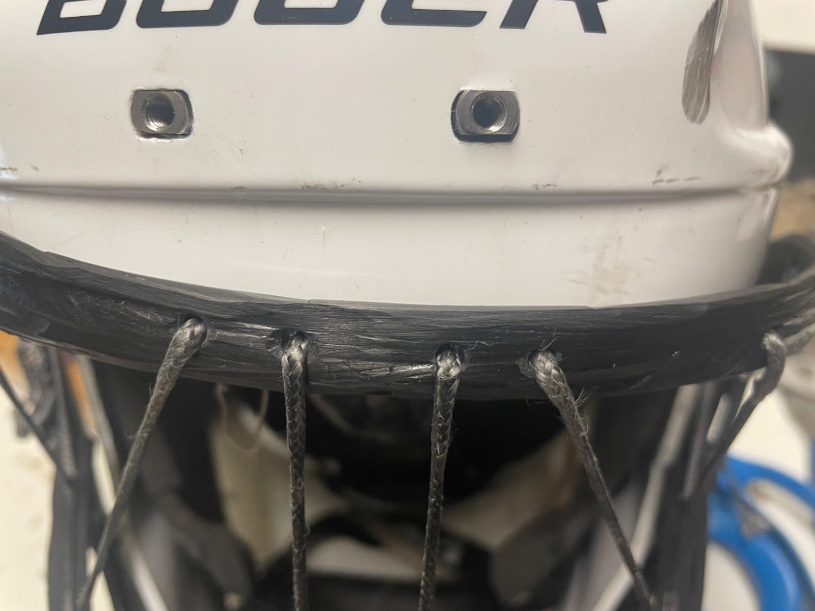
For instance, it’s impossible to model knots in engineering software. Had I started with a computer model, I would’ve ignored the knots and probably would’ve tried to optimize the placement of the strings or strength of the frame – things that I could see and measure in the program. As we know now, that would have been a bad move. Knots have presented the single biggest challenge so far.
So, why did I start using engineering software now? Because I needed to upgrade the outer frame of my cage. Now that I was able to add some serious tension into the strings, I was actually bending and compressing the frame.
I could have just made the frame beefier, but I wanted to take the opportunity to upgrade my manufacturing process. I’ve been making the frame from wet-lay carbon fiber tow, meaning that I’ve been wetting dry carbon fiber strands with resin by hand and placing them into a mold, a rough-and-ready cardstock contraption taped to the mask.
I wouldn't feel comfortable having someone wear that on their face. The wet-lay process is somewhat unreliable. The resin coverage of fibers can be inconsistent, leading to voids and air bubbles inside the part, where they are difficult to detect. Those air pockets turn into cracks, and cracks turn your single part into multiple pieces.
I thought about a few options.
Use the same wet-lay process, but upgrade the mold and use a vacuum bag, which compacts the composite and, theoretically, gets rid of the voids.
Use a prepreg composite. These are carbon fibers that are pre-impregnated with resin. With much better consistency than wet-lay processes, prepregs are now used in practically every non-hobby use of composites. The trouble is that they require an oven and, because of the heat, a more robust mold.
Switch to metal for the frame and crossbar. I could have some rod bent into shape just like it’s done on current cages.
You can see why I needed to make a CAD (computer-aided design) model. To upgrade my frame, I’d need to get a supplier to either make a mold or bend a metal frame.The best way to communicate with suppliers is through CAD.
I’ll get back to my model in a second, but first, I’ll talk through why I ended up deciding on option 3 – the metal frame.
This wasn’t an easy decision. I felt as though as I was letting go of a big part of my vision for the project by moving away from composites. I’d always thought of this cage as a bit of an art piece, showcasing how differently you can use fibers in a design. “Fibers Two Ways” if you will.
My main concern is the warning signs before failure. In a metal part, you would see the metal visibly bend and know that something is wrong. In a composite part, there could be small internal cracks that you wouldn’t see until it’s too late. It’s not that I couldn’t make a safe composite frame, it’s that it would take me much longer to get confirmation.
For a metal part, I could: build the part > test the cage > look for yielding > feel confident in the design.
For a composite part, I would: build the part > inspect for voids introduced in manufacturing > test the cage > inspect for voids / cracks > feel confident in the design.
Not to mention that I’d have to inspect every single composite frame that I built. So for now at least, I’m going with a metal frame and crossbar.
Here’s how I made the CAD model that I sent out for quotes.
I’ve been tempted to make more videos to share my progress, so please let me know how you liked this one!
Thanks for reading and watching,
Surjan
Software used: Ethan Makes 3D Scanner (Free to use, $7 to export), Onshape Free (Free), SimScale (Free)
The video is great.