#43 - Bend It Like a Beam
Leaf-Inspired Trunk Pt. 5
Previous Parts in This Series: Part 1: Intro, Part 2: Mold Unknowns, Part 3: Mold Attempt #1, Part 4: Mold Attempt #2
(Step 2 isn’t done yet, but I skipped ahead to 3 for now)
Considering that time has lost all meaning in quarantine, you may not have even realized that it’s been longer than usual between posts. And since we share a sacred bond -- the bond between a writer of a free newsletter and a reader who can come and go on a whim -- I feel I owe you an explanation.
I felt that I had gotten into a stale routine of writing a post every week whether or not I had something worth sharing. I felt I was turning into a newsletter writer rather than a guy who makes interesting things and shares his progress. Nothing wrong with being a newsletter writer, just not what I want to do. I was hoping that holding off on writing would free me up and then I would magically start flying through the project. But even with the new writing schedule, I still feel like I’m moving glacially slow. Oh well.
So what have I been up to? Well, I switched gears from preparing the trunk mold to working on the actual design of the trunk itself. In doing so, I’ve been trying to deepen my understanding about the nature of stiffness.
Bending
The first task was to translate my general desire to design a stiff trunk into something more definite. I chose to think about it in terms of closing an open trunk. I don’t want whatever trunk I design to bend significantly under the force I apply to close it. (That’s still a bit of a vague requirement, but it’s good enough for now.)
A trunk-shaped object is hard to think about at first, so let’s replace it with something simpler, like a rectangle.
In engineering, that rectangle is called a beam. My goal here was to understand what’s happening inside the beam, so I’d know what to fiddle with to make the beam, and ultimately the trunk, stiffer.
(A beam is a foundational mental model in engineering, and can be applied to a huge range of designs, so it’s worth learning and relearning. I recommend Gordon or the more technical Timoshenko and Den Hartog for further studies.)
The beam I’ve drawn experiences two main types of forces: bending and shear, and it’ll help to break those out and look at each in isolation to see how they affect stiffness.
Bending first. Grab an eraser and bend it so that it makes an upside-down U. You’ll notice that the top surface of the eraser stretches while the bottom compresses. Not a ground-breaking insight, but one that lets me start building my model.
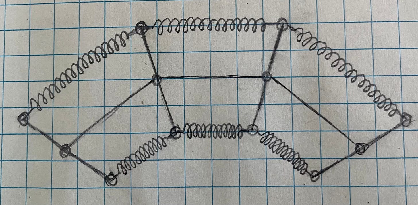
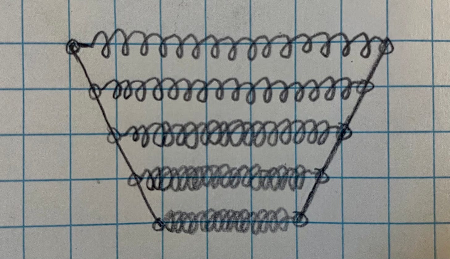
I’ll represent those surfaces that are stretching and compressing as springs. And to simplify how this representation behaves, I’m going to add another bar in the middle, like so:
That’s a good start but it doesn’t look anything like the eraser. It’s a trapezoid with no curvature. To get some curvature, I’ll break up the rectangle into smaller segments.
That looks like a very workable model. Now I can poke and prod to see how much the different factors -- like the geometry and the stiffness of the springs -- affect bendiness.
But first, how do I measure how much something has bent, so I can compare the effects of changing different parameters? There are a couple possibilities. I could measure (1) how far the beam deflects or (2) how tight the curvature of the beam is. I’ll go with option two for now, because it requires me to know less about the beam. The curvature accurately describes a beam of any length. The deflection only tells me about a beam of a particular length. I want to keep things simple, so fewer variables is better.
That tightness of curvature is more commonly called the radius of curvature. Imagine the beam growing long enough to complete a full circle. The radius of that circle describes the curvature.
It’s a tiny bit confusing that as the beam is bent more, the radius gets smaller. So I’m going to take the reciprocal of the radius. That way the measurement lines up better with what it’s describing.
So I have a measure for how bent the beam is. Now, I can start turning a few knobs and see what effects they have. I’m interested in building intuition, not in getting an exact solution, so the focus is on proportionality and order of magnitude effects.
The most obvious knob to turn is the angle of the trapezoid. I can see that the beam bends more when that angle, 𝜽, gets larger. As I said, I’m not worried about the exact relationship here, so I’ll just say that the amount of bend and the angle are proportional to each other.
What, in turn, affects the angle? As the height of the beam increases, the angle decreases.
The angle of the trapezoid is also affected by how much the springs on top and bottom stretch and compress. I’ll call this ΔL.
So far, we have this relationship.
But there’s one problem. ΔL isn’t a great description of how much those springs are stretching or compressing, because it doesn’t take into account how long the spring is. In other words, there’s a big difference between a 100-foot-long spring compressing an inch versus a 2-inch-long spring compressing that same inch. So, I’ll divide the change in length by the overall length. (I’m being unspecific if I’m talking about length of the segment or the length of the whole beam, because it doesn’t matter.)
I can plug that back into the relationship I established earlier.
This tells me some things already -- like that a taller beam bends less -- but I want to go deeper. I haven’t really poked around the springs much, so let’s do that.
The equation for a spring is pretty simple:
F is the force with which you push or pull on the spring, x is the distance that the spring is stretched or compressed, and k is a “spring constant”, something that tells us how stiff the spring is.
In my case, the spring is compressing or stretching ΔL instead of x.
I can also replace the force with something more useful -- namely, torque. Torque is also known as a moment of force, or, more commonly, a moment. Both force and torque could describe how hard you’re trying to bend the eraser/beam, so why bother substituting in a moment?
Because a moment describes your input no matter what the beam looks like; force is dependent on the beam’s geometry. Think of it as a door -- it takes a certain amount of moment (torque) to open a door. If you push close to the hinge, it takes more force. And if you push far from the hinge, it takes less. But the torque is the same in both cases.
In my case, the geometry of the beam affects where on the door I’m pushing. I want to separate out as many factors as possible so I can look at them in isolation. If I just say that the beam bends more with more force on the springs, it could mean one of two things: that I’m actually changing my input or that the geometry of the beam is changing. I need to split those apart. Let me show you what I mean.
The middle of the beam is like the door hinge. And the height of the beam is where along the door you push. The force and distance are essentially at right angles to each other, so I can say:
Plug that back into the spring equation:
And plug that back into the radius of curvature equation:
Phew. Let’s stop and think about what this means. Clearly the height is a much bigger factor than anything else. (This is the basic principle behind things like corrugated panels or even corrugated cardboard. Move more material away from the middle, and you’ll get more stiffness.)
The equation might be a little confusing in regards to length. From experience, longer things seem floppier. This equation seems to say that longer beams will bend less. Remember though, that this is assuming that the amount you’re bending the beam (the input) remains the same no matter the length of the beam. We’ll see later on that this is usually not the case.
But first I need to look at the other force present in my beam.
Shear
If height is so effective at making a beam stiffer, why is a stack of papers so floppy? Clearly, there’s something else at play besides bending.
One clue as to what’s going on is to pick up a softcover book. Along the spine, the book is stiff, but turn it ninety degrees and it’s hopelessly floppy. What’s the difference? In the first case, the pages cannot slide past each other because they’re glued together. In the second, the pages slide past each other freely.
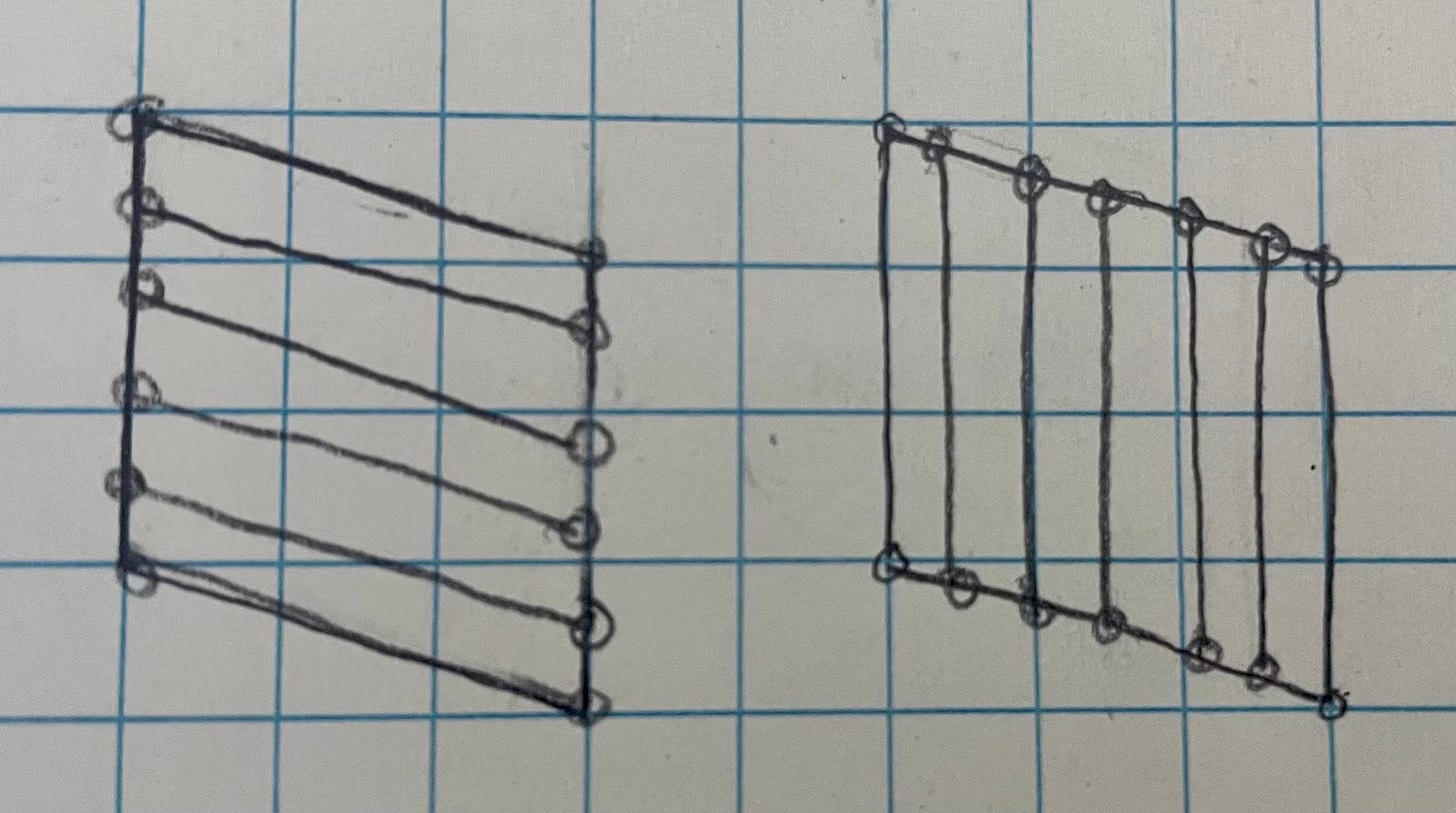
This new factor is called shear. Here’s how it’s usually shown.
You can see the two sides sliding past each other. To prevent that, we need some shear stiffness. But how does that shear stiffness develop?
Let’s start adding bars to see what will help prevent that motion. All of our bars will be pinned, so they’re free to rotate. That means they’ll only be able to push or pull, not bend. This simplification gives me a window into the way shear is resisted at the most elemental level. Atoms can only really push or pull each other. Shear, in reality, is just another mental model to simplify the world.
But let’s add bars and see what happens.
Adding horizontal or vertical supports does nothing, like adding more pages to a book. What does help is an X-brace.
You’ve seen this before. This is the basic concept behind trusses, which are used all over the place, most visibly in bridges.
Beyond that, there are no real geometric insights about shear like there were for bending. So we won’t do a long derivation, instead we’ll just think of the shear stiffness being provided by a shear spring. Sort of an “it’s a black box, I don’t care what’s going on inside” approach.
Shear and Bending Together
Beam bending, then, is some combination of pure bending (where the sides of the rectangle stretch and compress) and pure shear (where the sides or the rectangle slide past each other).
The next question is: how much shear vs pure bending is there in a beam? In other words, how much should I care about one vs the other?
Let’s take another look at those equations I came up with for bending and for shear.
Unfortunately, I can’t really compare the two to each other right now, because the shear equation is talking about how far the end of the beam drops while the bending equation talks about the radius of curvature. So I’ll try to find how far the end of the beam drops from pure bending.
I know it’s some combination of the radius and the length of the beam.
I might guess something like this.
But I know that’s not right, because the relationship between length and deflection is not linear. If it was, the beam would look like, well, a line and not a curve. There must be some BS with cosines and sines involved, but I’m trying to keep things simple here.
So I can use another trick, formally called dimensional analysis. Basically I just take a look at the units and see if they make sense. The deflection, length, and radius all have units of length (inches, mm, etc). That L/r equation I tried makes no sense because the units don’t match up:
Instead, I could do this:
It’s not exact, but it fits better than what I had. Plugging in my original bending equation, I get:
So the deflection of my beam is the bending and shear combined:
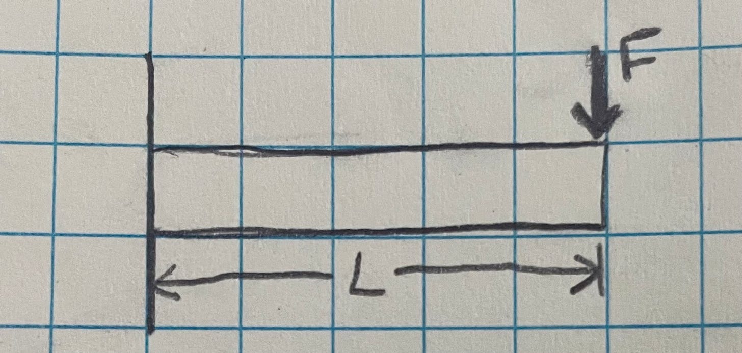
One last substitution will make it even easier to compare them to each other. You’ll notice that the input is force for the shear part and moment for the bending part. Let’s turn that moment into an equivalent force. I revisit my beam for a moment.
At the base of the beam, I can reason that the moment is the force applied times the length of the beam. But as I go out towards the tip of the beam, the beam is effectively much shorter. So the end of the beam is experiencing much less moment than the base.
Think of it as holding a broom straight out in front of you with one hand. The moment is how much the broom is twisting your wrist as you try to hold it up. If you move hand further down the broom, the less the broom will fight you. You’ve reduced the leverage and the moment.
So the moment looks something like this along the length of the beam.
I’ll take the opportunity to add a quick word about shear. The shear doesn’t vary along the length of the beam. Coming up with an analogy is a bit more difficult here, but I’ll give it a shot anyway. Imagine you had two broom handles held out in front of you, one on top of the other. You’re holding the ends just from the sides, your hands together like in a forceful prayer (told you an analogy was difficult). As the broom handles droop, they slide past each other. The amount they slide past each other does not change over length of the broom. The amount they shear past each other does not change over the length of the broom. So in order to keep them from shearing past each other, the shear force would be constant.
So I know how the shear and moment are distributed along the beam. But why did I come down this path anyways? Oh yeah, I was trying to recast the input in my pure bending equation from a moment to a force.
The moment diagram tells me that the moment varies along the length from FL to 0, but I’m just going to simplify it to M = F*L. (I’ll reemphasize that I’m only looking for an order of magnitude level insight here.)
So very roughly I can say that the bending stiffness is L²/h² more important than the shear stiffness. In the case of my trunk, the “height” is the thickness of the trunk, so that’s roughly:
~9000 times more important. So I can essentially ignore the contribution of shear stiffness. As long as I have some sort of shear tie, I’ll be fine.
Examples
Now that we’ve gone over some basic concepts, we should be able to understand the reasoning behind engineering staples, like the I-beam.
A tall beam is good at resisting bending. But why the “I” shape instead of just a tall rectangle shape? In my model, I only had a single spring at the top and one at the bottom of my rectangle. A better approximation would be to fill the whole thing with springs.
From my earlier equation, we’ve already seen that the beam’s stiffness is proportional to h²k. I was then considering the impact of height and stiff materials on the beam as a whole. But the h²k term also reveals more. When we thing of the beam as having more springs, as above, the h²k term tells us how important each spring is.
The springs at the top and bottom of the beam are far more important to bending stiffness than the ones in the middle. This makes sense visually too -- the springs on top and bottom will stretch more than the ones in the middle.
So we’ll get much more bang for our buck from stiffening up the springs on the top and bottom rather the ones in the middle. But how can one “stiffen the spring” in real life? Answer: either by choosing a stiffer material or by having more of the material. Aha! That’s why I-beams have that “I” shape.
Mechanical engineering is often, at its most basic, rearranging material in the most efficient way possible. Adding material in the middle of a beam wouldn’t add to its stiffness as much as it would to the top and bottom. The middle of the beam is kept as thin as it can be, while still retaining enough strength and stiffness to keep the top and bottom of the beam from shearing/sliding past each other.
It would sure be nice if there was a way to describe the geometry of a cross-section that takes into account its height and its area. Something like Area x h² perhaps. Well, we’re in luck! That’s exactly what’s described by the area moment of inertia. It’s no different to what we’ve just gone through. Except instead of breaking up the beam up into a few springs, the moment of inertia represents the beam as an infinite number of infinitely small springs.
Let’s look at another example -- the spar of a composite aircraft.
A spar is a beam inside a wing that’s responsible for reacting to the aerodynamic forces that are trying to bend the wing. When it’s made of composite, it’s typically a C-shape and not an I, because it needs to be removed from a mold. The general concept still applies though -- maximize the amount of material at the top and bottom of the beam.
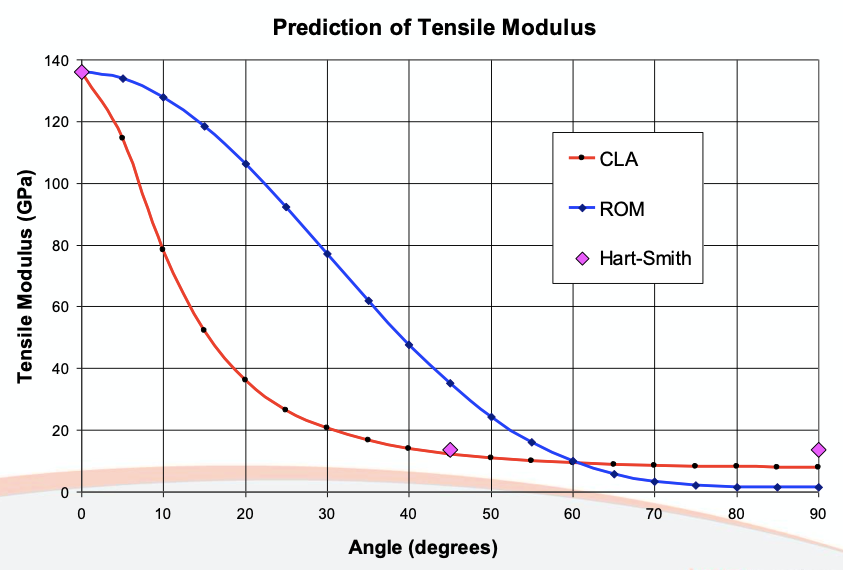
The cool thing about composites is that you can also tailor the material. By aligning the fibers in a particular direction, you can dramatically change the stiffness. How dramatically? I couldn’t find experimental data, but below is a chart showing a few different methods of predicting that stiffness.
It should be no surprise that the top and bottom of a spar -- the caps of the spar -- would be full of fibers aligned along the length of the spar. And the middle -- the web -- has fibers oriented at a 45° angle to take the shear (remember the truss structure of the bridge).
The Vein Concept
We’re feeling pretty decent about our grasp of the concepts now, so let’s try venturing onto some new ground.
The inspiration behind this whole thing was Bcomps' powerRibs™. They use essentially a thick yarn on top of a flat composite. When I first thought about the project, one of the things I was excited about was how the twist in the yarn mimicked a truss structure. Aligning the fibers closer to a 45° would increase the shear stiffness.
But after going through that equation-deriving ordeal I’ve just put you through and seeing what little impact the shear stiffness had compared to the bending stiffness, I started having major doubts about the idea.
It’s not that the yarn-veins wouldn’t add any stiffness. They would -- it’s just that there’s already a widely used, existing solution that could add it more efficiently: core.
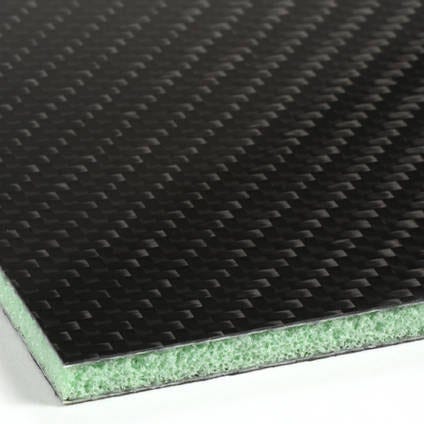
Core is a lightweight material (foam, balsa wood, nomex honeycomb, etc.) that’s sandwiched between composite layers. It adds height without adding much weight -- think of it like the tall skinny bit of the I beam. Its job is to space out the stiff springs as much as possible.
So what about core made me doubtful about the yarn-veins? The density. Core is roughly 10 times less dense than fiber.
Just from a glance, you can see this is a clear win for the core. We’ve seen that height has a disproportionately big effect on stiffness. Even if the yarn-veins were 10x stiffer in shear, they couldn’t make up the deficit in height.
At this point, I was ready to call it quits on the vein idea. But after talking about what I’d learned with my brother (since I didn’t have a rubber duck handy), I realized it was only one aspect of the idea that was flawed. There were still other things to explore.
One of the things that the leaf veins got me thinking about was distributed vs discrete approaches to stiffness. Core is a distributed approach to stiffness. The whole panel has the same increased thickness and, consequently, the same increased stiffness. What would happen if you concentrated the stiffness in a few “veins” and left the rest of the panel unstiffened? Would the panel as a whole be more or less stiff?
The comparison has to be a fair one, so each panel must be the same weight. The difference between the distributed and discrete is the amount of core. We’ll add the weight of that removed core as fibers on top of the remaining core.
Unlike the yarn vs core comparison above, this one isn’t eyeball-able. We’ll have to use that moment of inertia concept we talked about earlier. Remember, moment of inertia is a property that tells us only about the geometry of the beams we’re comparing -- more area further away from the middle gives us a higher moment of inertia and a stiffer beam.
But because it’s a purely geometrical property, how do we take into account that we’ve got two different materials in our cross-section -- the low density core and high stiffness composite? Remember that stiffness is related to h²k. We equated the k roughly to A*(material stiffness). We can take advantage of that here.
We can take a less stiff material, like core, and find an equivalent amount if it was something stiffer, like composite.
Plugging in material stiffnesses (Young’s modulus) from the internet (this for the core and this for the flax fiber which makes up most of my composite), we can see that the effective area, when translated from core to composite, is really small. By the way, if you draw that out, you get something that resembles an I-beam.
In fact it’s so small, it makes next to no difference whether we include it or not. I did the math -- the difference was 0.0015%. I think you’ll agree that’s basically nothing. For simplicity, we’ll just ignore the contribution of the core entirely.
And now that we’ve got the concept behind moment of inertia locked down, there’s no reason not to take a shortcut in calculating it.
Thankfully most CAD systems (except for Onshape -- what are you doing?) have a feature that can calculate the moment of inertia. So I fired up Solidworks, which I definitely paid $4k for, and sketched out the panels.Here’s the full width.
And core that only takes up 50% of the width.
I did that a few times and plotted the trend.
Again, this is with taking the weight saved from removing core and adding more composite on top. The way it’s set up, you’d have infinite stiffness with no core, because the model thinks that you’ll have an infinitely tall beam. But the trend is still very interesting even in the more reasonable 30-50% range. It appears that concentrating stiffness discretely is a good way to go.
But, I hear you ask, won’t the parts without core be really floppy? They will certainly be floppy, but everything is relative. We just need to make sure that it’s not more floppy than the fully cored version. In other words, we need to make sure that the floppy bits don’t ruin the advantage we get from the extra stiff bits.
So we need a new mental model for this. Here, we can draw on an engineering saying -- “stiffness attracts load”. (I wrote a whole post about it. Think of it like springs, if you have two springs of the same length but different stiffness being pulled the same amount, more of the force will go into the stiffer spring.)
If we pull on the flexible part of the beam, the load essentially has two paths it can take. A long one all the way along the beam to the support, or a short one to the vein.
We can think of those load paths as beams of their own. From our earlier efforts, we know that a shorter beam is stiffer. So we expect that the load would prefer to follow the shorter, stiffer path and dump into the vein.
Going back, let’s prove that this added deflection from the core-free areas doesn’t torpedo our idea completely. To do that, we’ll solve for the deflection of a fully cored panel to get a baseline. Then, we’ll calculate how far from the vein we can apply the force before the deflection exceeds the baseline. If the un-cored area can only extend a fraction of an inch beyond the vein before it gets too floppy, the veins would have to be so densely packed that there would be no advantage over a fully cored panel.
We’ll use “real” engineering equations since we’re plugging in actual numbers. L is the length of the trunk and I is the area moment of inertia, which I took from the Solidworks sketches.
That seems reasonable to me. This means that the veins could be spaced six inches apart -- far enough that less than 50% of the panel would be cored. That means that more weight is available to stiffen the veins and, as you’ll remember from the “Stiffness Improvement vs Core Width” chart, that the trunk as a whole will be stiffer.
The vein idea is looking good again.
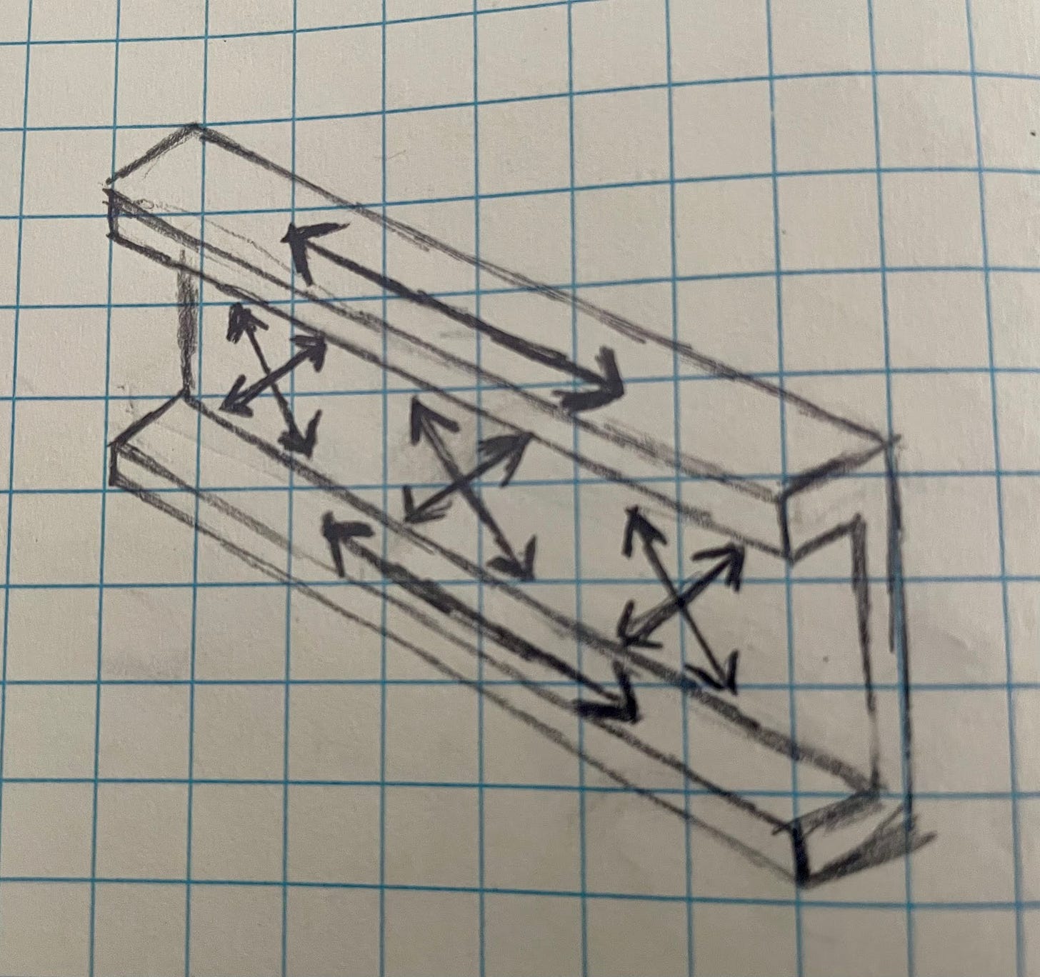
So far, we’ve only thought about beams. Let’s expand that out a bit wider. If I made a trunk with stiffeners all parallel to each other, it would be pretty stiff along those beams, but not so stiff perpendicular to them. Think corrugated cardboard, but more extreme.
The obvious solution is to add more veins in that other direction, making a grid. But this is a leaf-inspired project and so, we scorn right angles.
I tried to find an explanation for why leaf veins are angled, but it was more difficult than I’d anticipated. First off, in turns out that the angle is not necessarily consistent within a leaf, much less leaf to leaf.
And then, the mentions I did find of the angle were not related to stiffness, but to its effect on the flow of water and nutrients and on the geometry of an unfolding leaf. The resources I did find on the structure of leaves seemed to focus on the primary “vein”, the petiole, as the only noteworthy structural support. The petiole was, of course, modelled as a beam.
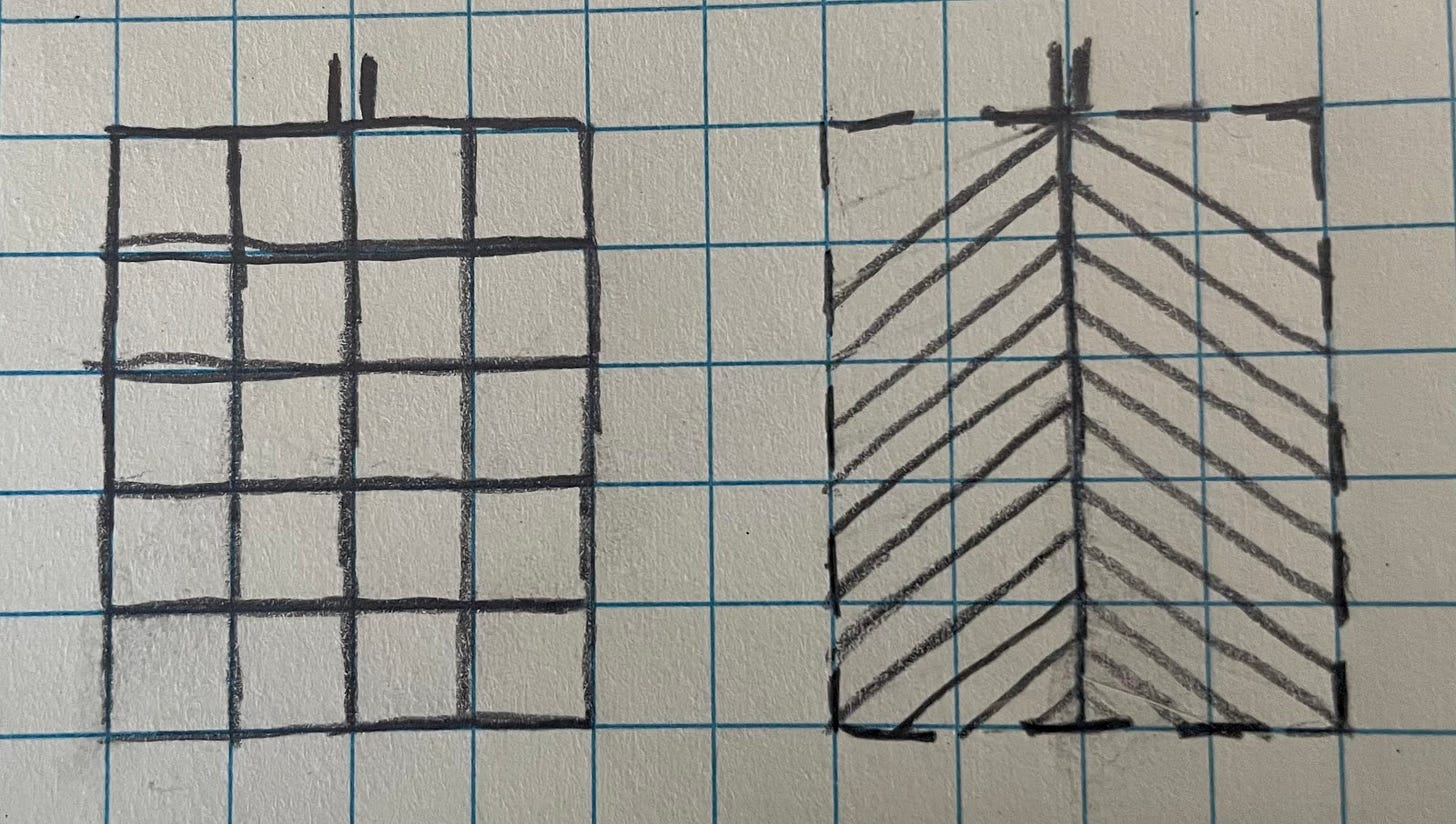
Without any help from papers, we’ll have to think for ourselves. Let’s make a simple representation of what we’re comparing - one rectangular leaf with a grid of veins, and one rectangular leaf with a more natural set of veins.
You’ll notice that the “leafy” veins are also spaced a little closer than the grid ones. To make it a fair comparison, the sum of the lines in both patterns add up to the same length (ie, the same weight). The leaf veins don’t have the extra vertical lines that the grid does, so their lines can be closer together.
What we’re looking for is to see: if we start anywhere in that rectangle and only travel along the lines (grid or leaf vein) what gives us the shortest path back to the support?
Why do we care about the shortest path? Because it’s the stiffest. Remember that a longer beam deflects more that a shorter one. Or that a long rope stretches more than a short one. And how can we be sure that the load will travel along the vein? Because stiffness attracts load.
Alrighty, so we know why we’re aiming for the shortest path. Now we just have to make the comparison. Let’s pick an arbitrary point and trace the path to the support.
You can see that on the grid, we have to travel over two and up three. No matter what path we take in the grid, that’s the length of the path. On the leaf vein, remembering 3-4-5 triangles, we travel diagonally 2.5 and up 1.5. The vein path is shorter.
On further thought, it becomes apparent that this is true of any spot we pick. On the grid, we’ll always have to go over and up the full distance. The veins will always have the hypotenuse thing going for them. And because the veins are spaced close together, if we pick a point that’s not on our pattern, the distance to the nearest vein is shorter on average than it is to the nearest gridline.
Another point in favor of the veins.
One last advantage is the ability to tailor the stiffness of the composite. With the veins making distinct beams, I can more easily align the fibers of the composite along the veins -- like the example of the spar earlier. With a cored panel, there’s no distinct load path, and so, no easy way to align the fibers. This is a really interesting concept, but to be honest, I’ve run out of steam on the explanations a bit, so I’ll just leave it at that for you to mull over.
To sum up this absurdly long post, I think I can take a few leaf inspired principles and make a lighter and stiffer trunk than a normal cored panel. Next step is to prove it.
I love when readers get in touch. Leave a comment, reply to this email, email me at surjan@fastmail.com, or find me on LinkedIn.
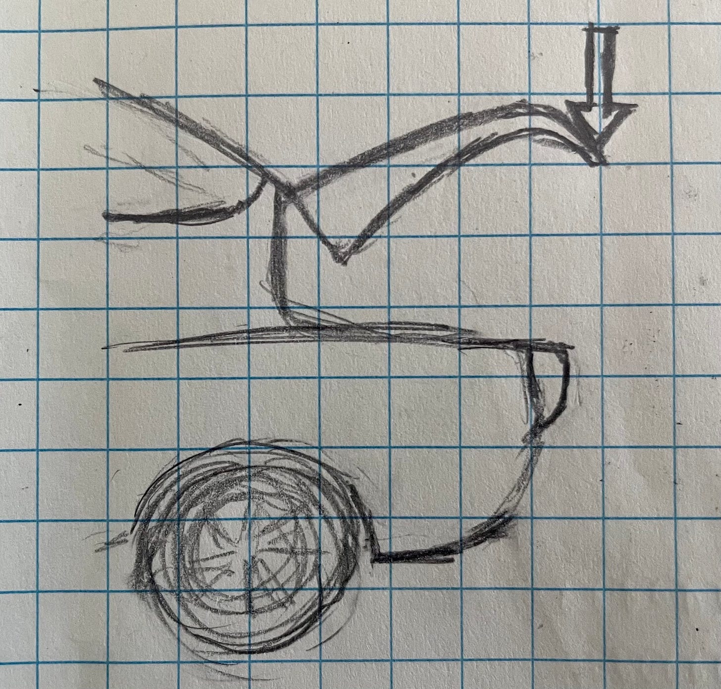
Drawing exercise #32. If you missed it, here’s why I’m learning to draw.

















Very instructive. I rarely/never do much with Saab parts, but I do make telegraph keys. Specifically, 3D printed versions. Virtually all keys are metal, usually brass. Trying to get the same stiffness with plastic was a challenging for me. Essentially, the key is made of beams. The process can print a beam as a solid which is very wasteful of material. But it can also print just solid walls with "infill" patterns inside that are basically a less dense core. Intuitively, I understood some of that was going on, but I new there was more. This study provided a lot of the missing pieces for me.
If you're interested, here's a link to a photo album of the latest key. It's loosely patterned on a Russian WWII semi-automatic key.
https://photos.app.goo.gl/EQF8ZGZZ6VMZCb6z5
Thanks for posting your studies. They are always interesting. I often learn a great deal from experiencing someone's thought processes even if I can't use the material directly.